Modernizing An Old Classic
We have just completed the second project in the Academy for the 2014-15 school year. It was a huge success! This project takes a classic physics project and “upgrades” it by incorporating modern engineering design technology and fabrication techniques.
We started with a great project that is now available online through Engineering Encounters. This was a project that was originally published by Stephen J. Ressler of the United States Military Academy. It is a rigorous approach to designing and building bridges from file folders:
https://bridgecontest.org/resources/file-folder-bridges/
Its a great project with an incredible set of resources, background information, and step by step instructions. Unlike less rigorous and involved bridge design projects (using toothpicks for example), this project has the students building compression members (beams) and tension members (cords) and gussets to better model real world designs and to give the students the opportunity to learn and make decisions about which members to use in different parts of their own designs.
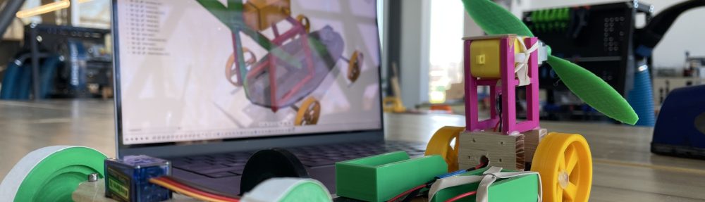
The only issue that we had with this project is that it requires the rather tedious process of having students trace out the unfolded beam designs onto file folder material and then use scissors and blades to cut out each beam and cord. But we have a laser cutter! There had to be a way to incorporate both 3D CAD design and our laser cutter in order to modernize this process. We also knew that Autodesk Inventor had some really amazing tools for analyzing design structures.
From Sheet Metal To Manila Folders
Autodesk Inventor has an amazing set of tools for designing sheet metal parts. Using these tools, an engineer can construct 3D models made of folded metal parts made from just about any thickness of metal stock. Once you have designed the folded metal part, Inventor will create a flat pattern design for you that you could then send to a CNC plasma cutter to cut from sheet metal stock. You would then fold the part up manually and you would have your folded part.
Inventor gives you the ability to custom define the thickness of your stock, and some of the parameters around how it can be bent. We defined our stock to be as thick as manila folder paper. The next step is a bit tricky, but with the help of a great video I came across from Rob Cohee, we were able to define custom folded paper beam stock that the students could then use to build out their frames. Once again, Inventor has an amazing set of tools for defining structural frames (called The Frame Generator) that can then be populated with any kind of structural beam. You can also define your own structural beams that can be used to populate your frame.
I have included a video below that we use with the students to help guide them through this process:
Using the frame generator tool in Inventor also allows the student to miter and trim the beam members, which allows the students to focus on design rather than getting lost in the time consuming process of calculating the cut angles. The following video shows you how this can be done:
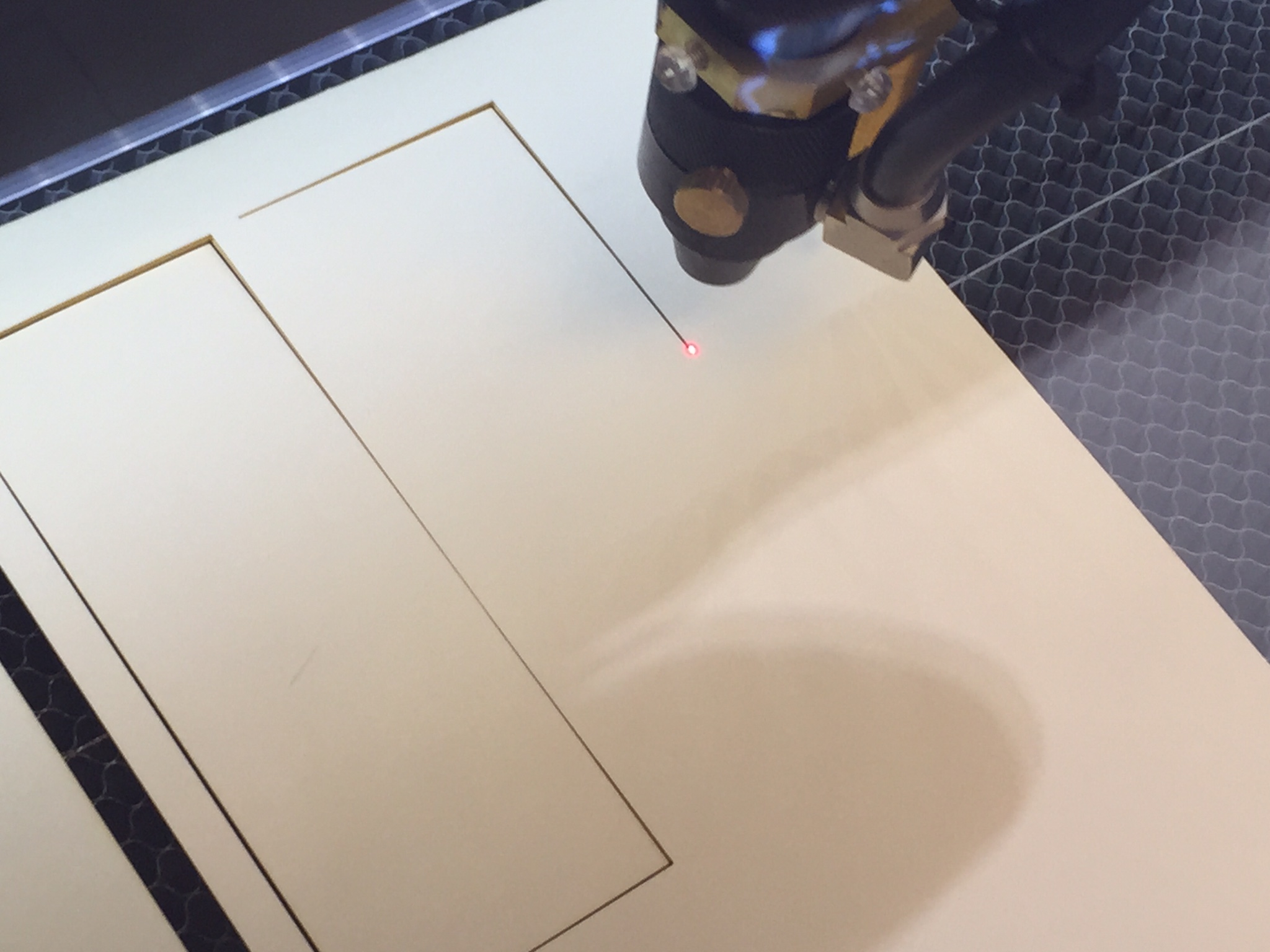
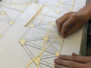
Once the students had designed the bridges, it was time to prepare the flat patterns and have the laser cutter do the work of cutting them out.
Fold, Glue, Repeat. (Some Assembly Required)

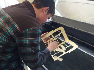
The students prepare their flat pattern cut-outs for the laser cutter and then you let the laser “rip”! Its awesome to sit back and watch this machine cut. I never get sick of watching it! Having the students do this would take SO much longer, the cut parts would be less accurate, and as all CTE teachers know, one of the most dangerous tools in the shop is an Exacto blade.
Some might argue that the “manual” process of cutting all these beams out by hand is “good for the students”, but we feel that saving time here allows us to use that time in other areas, such as virtual testing. Before the students get to build their design, we ask them to use Inventor’s frame analysis tools to help them analyze potential weaknesses in their designs. The following video shows just how amazing this tool is:
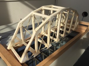
Once the students have done their analysis and cut their construction members, its time for folding and gluing, and folding, and gluing, and … At this point our project does not differ from the Engineering Encounters project. The students use a sheet of paper (actually two 11 x 17 sheets) with an elevation view (printed from Inventor as a CAD drawing) glued to a board as a guide for assembling the beams, cords and gussets:
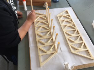
This process goes relatively quickly as the students have done all the prep work to make sure that the pieces all fit together. Once again, this really demonstrates how modern technology can allow the students to focus their attention on design.
To Break Or Not To Break
Once the bridges are assembled, its time to test them out. The performance metrics for the contest are not actually based on the strongest bridge but rather a more realistic approach. We have attached a monetary value to each beam, gusset and cord. The bridges are then tested to a set value – the required load. The bridge that holds that load and is “manufactured” least amount of money is then given the highest marks.
Once the bridge has been tested at the required load, we then give the students the choice to see just how much the bridges can hold before catastrophic failure. Most students (encouraged by both peers and staff!) decide to take their bridge to the limit.
Its always a fun way to end the project!